Product details:
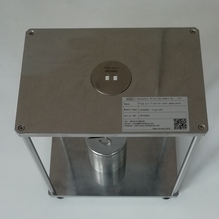
This device conforms to the standard of IEC 60884-1 Figure30. It is used for testing the firmness of the plug and the plug pin. The plug is placed on a rigid steel plate provided with holes suitable for the pins of the plug. The distance between the centres of the holes shall be the same as the distances between the centres of the circle circumscribed around the cross-sectional area of each pin in the standard sheet of the plug.
Each hole shall have a diameter equal to that of the circle circumscribed around the cross-sectional area of the pin plus (6 ± 0,5) mm.
The plug is positioned on the steel plate in such a way that the centres of the circles circumscribing the pins coincide with the centres of the holes.
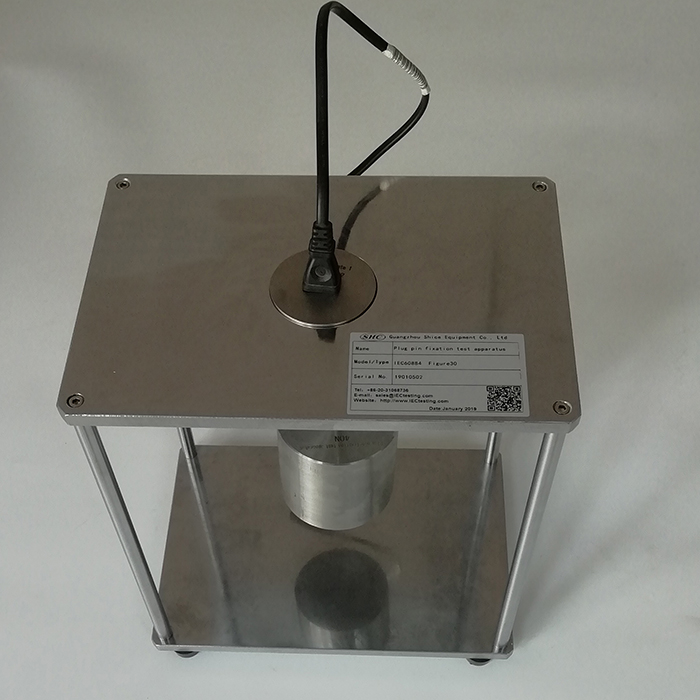
A pull P equal to the maximum withdrawal force as given in table 16, is applied, without jerks, for 1 min on each pin in turn, in the direction of the longitudinal axis of the pin.
The pull is applied within a heating cabinet at a temperature of (70 ± 2) °C, 1 h after the plug has been placed in the heating cabinet.
After the test, the plug is allowed to cool down to ambient temperature and it shall be verified that no pin has been displaced in the body of the plug by more than 1 mm.
Technical parameters:
Number of test station: 1
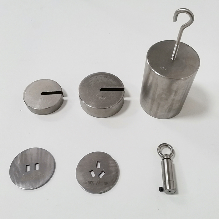
Weight: 50N*1, 20N*2, 30N*1, 4N*1
Standard Socked: BS socked*1, USA socked*1
Conforms to standard: IEC 60884-1 Fig30, VDE0620, BS1363
IEC60884-1 Mechanical strength
Clause 24.10 This test is made on new specimens.
The plug is placed on a rigid steel plate provided with holes suitable for the pins of the plug as
shown as an example in figure 30.
The distances between the centres of the holes (for example, d1 and d2) shall be the same as
the distances between the centres of the circle circumscribed around the cross-sectional area
of each pin in the standard sheet of the plug.
Each hole shall have a diameter equal to that of the circle circumscribed around the crosssectional
area of the pin plus (6 ± 0,5) mm.
The plug is positioned on the steel plate in such a way that the centres of the circles
circumscribing the pins coincide with the centres of the holes.
A pull P equal to the maximum withdrawal force as given in table 16, is applied, without jerks,
for 1 min on each pin in turn, in the direction of the longitudinal axis of the pin.
The pull is applied within a heating cabinet at a temperature of (70 ± 2) °C, 1 h after the plug
has been placed in the heating cabinet.
After the test, the plug is allowed to cool down to ambient temperature and it shall be verified
that no pin has been displaced in the body of the plug by more than 1 mm.