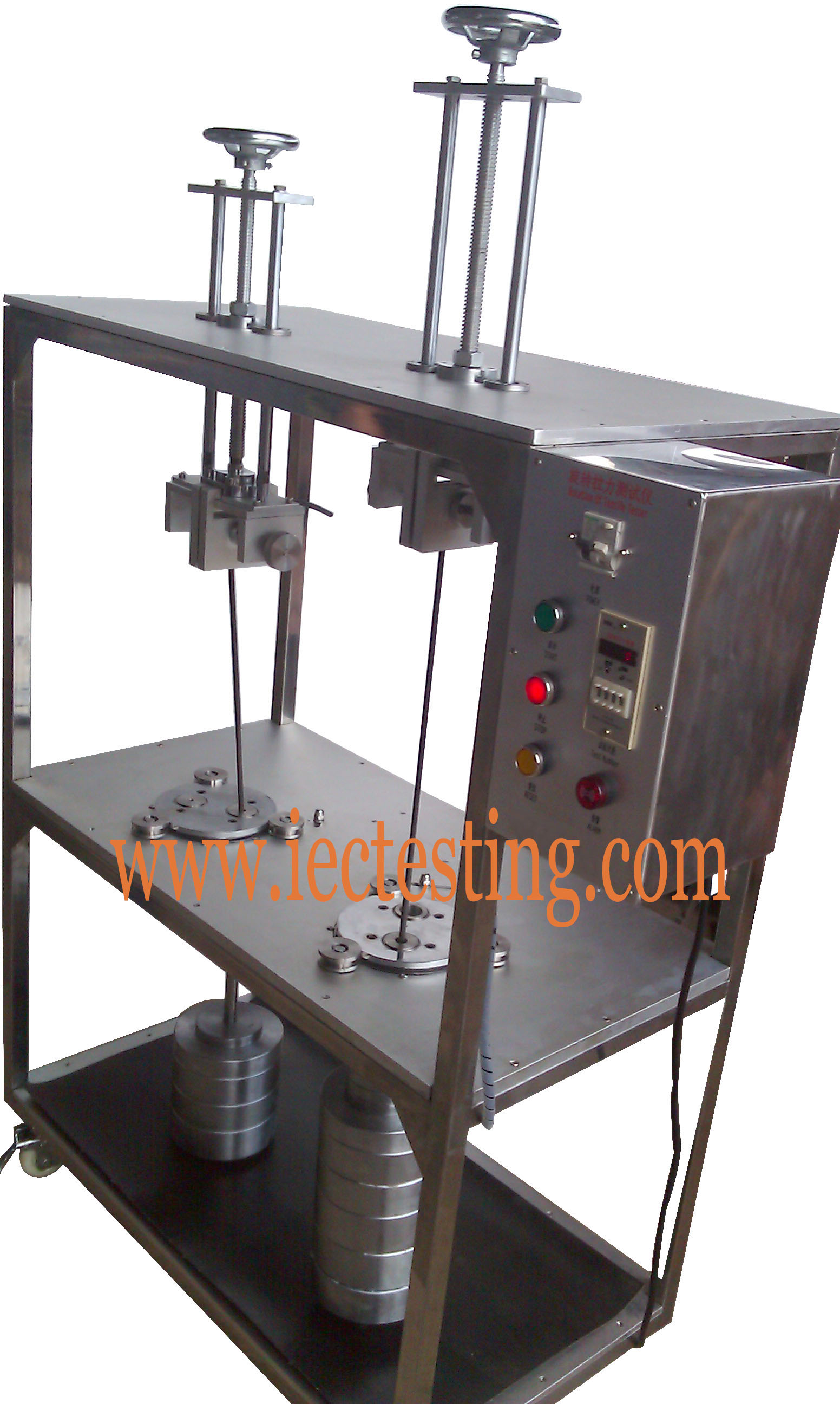
Product overview:
This testing machine is also called the test apparatus for checking damage degree of wire which confirms to UL486 standard. This compliance is used for judging whether the design and the structure of the clamping screw terminal is correspondent with the requirement of non over-damage to the wire. Besides, it is also used to check whether the clamping screw terminal can bear the stress during the process of normal usage.
The testing times can be preset before the test, and the compliance stops automatically with the alarm when the testing times are reached.
The major difference between SC-XL02 and SC-XL04 is that the SC-XL04 has two stations. The height can be reached to a maximum of 500mm and the maximum rotating weight is 22.7kg and the maximum tensile weight is 578N. It depends on the actual use to choose them.
Technical parameters:
1、power supply:AC 220V 50HZ
2、Rotating weight:9±1 round/min
3、The range of counting number: 1~9999(150 times(15 min) is by default.
4、Rotating weight: 32pcs.
5、The rotating diameter:76mm
7、The diameter of the Ferrule Hole:6.4、9.5、12.7、14.3、15.8、19.1、22.2、25.4、28.6mm
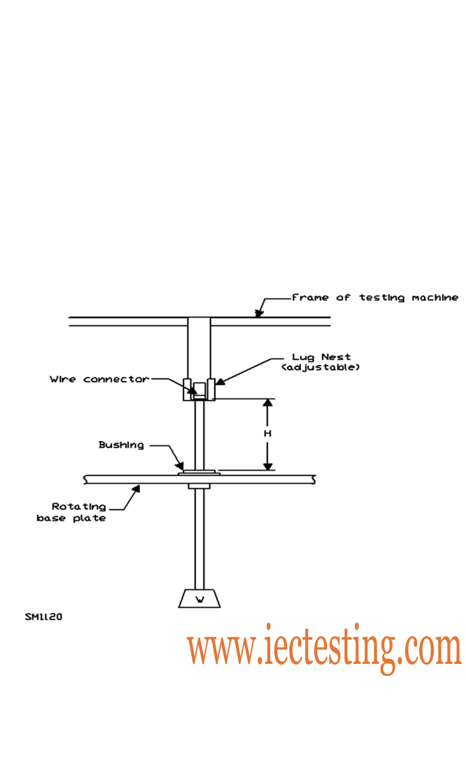
7、Height(H)(mm):260-500mm,electrodeless can be adjusted
8、Size:940mmX500mmX1300mm
| Size of conductor | Diameter of bushing holea | Height | Mass | ||||||
| Copper | Aluminum/Copper-clad aluminum | ||||||||
| AWG or kcmil | (mm2) | mm | (in) | mm | (in) | kg | (lb) | kg | (lb) |
| 18 | (0.82) | 6.4 | (1/4) | 260 | (10-1/4) | 0.9 | (2) | – | – |
| 6 | (1.3) | 6.4 | (1/4) | 260 | (10-1/4) | 0.9 | (2) | – | – |
| 14 | (2.1) | 9.5 | (3/8) | 279 | (11) | 1.4 | (3) | – | – |
| 12 | (3.3) | 9.5 | (3/8) | 279b | (11)b | 2.3 | (5) | 0.7 | (1.5) |
| 10 | (5.3) | 9.5 | (3/8) | 279b | (11)b | 2.3 | (5) | 0.7 | (1.5) |
| 8 | (8.4) | 9.5 | (3/8) | 279b | (11)b | 3.6 | (8) | 1.4 | (3) |
| 6 | (13.3) | 12.7 | (1/2) | 298b | (11-3/4)b | 8.2 | (18) | 4.5 | (10) |
| 4 | (21.2) | 12.7 | (1/2) | 298b | (11-3/4)b | 13.6 | (30) | 6.8 | (15) |
| 3 | (26.7) | 14.3 | (9/16) | 318 | (12-1/2) | 13.6 | (30) | 6.8 | (15) |
| 2 | (33.6) | 14.3 | (9/16) | 318 | (12-1/2) | 13.6 | (30) | 6.8 | (15) |
| 1 | (42.4) | 15.8 | (5/8) | 343 | (13-12) | 22.7 | (50) | 11.4 | (25) |
| 1/0 | (53.5) | 15.8 | (5/8) | 343 | (13-1/2) | 22.7 | (50) | 11.4 | (25) |
| 2/0 | (67.4) | 19.1 | (3/4) | 368 | (14-1/2) | 22.7 | (50) | 11.4 | (25) |
| 3/0 | (85.0) | 19.1 | (3/4) | 368 | (14-1/2) | 27.2 | (60) | 13.6 | (30) |
| 4/0 | (107) | 19.1 | (3/4) | 368 | (14-1/2) | 27.2 | (60) | 13.6 | (30) |
| 250 | (127) | 22.2 | (7/8) | 406 | (16) | 27.2 | (60) | 13.6 | (30) |
| 300 | (156) | 22.2 | (7/8) | 406 | (16) | 36.3 | (80) | 18.2 | (40) |
| 350 | (177) | 25.4 | (1) | 432 | (17) | 36.3 | (80) | 18.2 | (40) |
| 400 | (203) | 25.4 | (1) | 432 | (17) | 36.3 | (80) | 18.2 | (40) |
| 500 | (253) | 28.6 | (1-1/8) | 464 | (18-1/4) | 45.4 | (100) | 22.7 | (50) |
| 600 | (304) | 28.6 | (1-1/8) | 464 | (18-1/4) | 45.4 | (100) | 22.7 | (50) |
| 700 | (354) | 31.8 | (1-1/4) | 495 | (19-1/2) | 45.4 | (100) | 22.7 | (50) |
| 750 | (380) | 31.8 | (1-1/4) | 495 | (19-1/2) | 49.9 | (110) | 25.0 | (55) |
| 800 | (406) | 34.9 | (1-3/8) | 540 | (21-1/4) | 49.9 | (110) | 25.0 | (55) |
| 900 | (456) | 34.9 | (1-3/8) | 540 | (21-1/4) | 49.9 | (110) | 25.0 | (55) |
| 1 000 | (508) | 38.1 | (1-1/2) | 565 | (22-1/4) | 49.9 | (110) | 25.0 | (55) |
| 1 250 | (635) | 44.5 | (1-3/4) | 660 | (26) | 70.4 | (155) | 34.1 | (75) |
| 1 500 | (759) | 50.8 | (2) | 711 | (28) | 81.7 | (180) | 40.9 | (90) |
| 1 750 | (886) | 54.0 | (2-1/8) | 762 | (30) | 93.1 | (205) | 45.4 | (100) |
| 2 000 | (1 010) | 54.0 | (2-1/8) | 762 | (30) | 109.0 | (240) | 54.5 | (120) |
| a If a hole with the diameter given is insufficient to accommodate the conductor without binding, a bushing having a hole of slightly large diameter shall be allowed to be used. | |||||||||
| b For 12 – 4 AWG (3.3 – 21.2 mm2) aluminum conductor, use 318 mm (12-1/2 in). | |||||||||
Picture view: